Project Description
In this open-ended project, we were to brainstorm a list of problems that the world faces, whether it be the most pressing or frivolous, and select a particular issue, as well as a group, to pursue a close-to-complete or complete solution, using the enginnering design cycle, for our chosen problem. Our group aimed at designing a better bridge.
Key Concepts and Terms |
The Process |
Engineering Design Cycle:
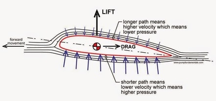
Nitinol: an alloy of Nickel and Titanium that has the property to return to its predetermined shape after heating. Fluid Dynamics: A subdiscipline of fluid mechanics that deals with fluid flow—the science of fluids (liquids and gases) in motion. Bernoulli's Principle: The principle in hydrodynamics that an increase in the velocity of a stream of fluid results in a decrease in pressure. Aerofoil: a structure with curved surfaces designed to give the most favorable ratio of lift to drag in flight, used as the basic form of the wings, fins, and horizontal stabilizer of most aircraft. 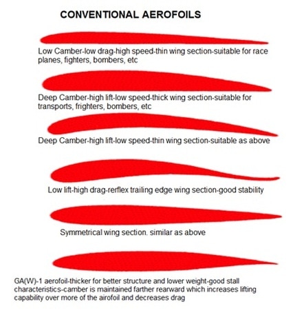
|
Many needs were identified during the class brainstorming session, and later individual groups focused on a specific issue, ours was improving a bridge's resistance to factors that could destroy them. From here, each memeber of our group, Josh Franks, Ryan Loeber, Tak Maga, Jackson Hilton, and myself, had researched the types of bridges, factors that affects a bridge life, potential shapes for the pillars of the bridge, materials that are currently used and could be considered for our bridge and the cost, and the legal standards for a bridge. To conclude the research phase, we shared out our findings to all members of our group to begin the process of thinking about how we could adresss flaws of current bridges. Then we came up with a collective idea of the solution, and began to run tests to understand which pillar shape woud bring about the best flow of water, using clay and water to see which shape brought the least amount perpendicular water against the pillar, with the best flow. After the tests have been conducted we realised we could have used a symmetrical aerofoil shape for the pillar, but we continued with our elliptical pillar as we thought it would be more stable. Then we created the prototype of the 80 ft span beam bridge segment on Autodesk Fusion 360 3-D modeling software, and tested it under the software's computer-simulted stress, pressure, and saftey tests, which it had passed. The design can be viewed by clicking on the button below, as the test can be found below.
After all of this, we made a Google Slides presentation that adresses how our bridge responds to heavy water currents, fire, earthquakes, and found the materials cost of the bridge, which is noninclusive of labor costs, and presented it to the class, which opened more ways to rethink our design, especially in regards to earthquake resistance and cost. One possible solution that we have considered to lower the costs of the bridge is to incorporate the Nickel-Titanium alloy into the framework of the bridge, like the inside of the pillars and deck. This makes it so that we would use less material, but enough so that the strength of the bridge is still not compromised. Parts of a Bridge:
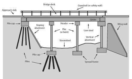
| |||||||||||||||
The Presentation
Presentation Notes
When we looked into some of the problems with these bridges, we came up with list of three problems that we thought we could address. The first problem is the force that a flowing river exerts on the pillars of a bridge, or the hydrodynamics of the bridge. The second problem, one extremely relevant in our area, is earthquake resistance. An earthquake can easily shake apart a bridge, and is not easy to address. Our third concern was fire resistance.
The problem is that the current of a flowing rivers creates water pressure on the columns of the bridge, causing them to collapse. To fix this problem, many different methods have been tested. Some of these methods are simply reinforcing the pillars or trying to ease the flow of the water with various mechanisms. The solution we went with is changing the pillar shape to split up strong water currents. This works by creating a football shaped pillar pointing into the current, that divides the current, forcing the strong water to flow around the pillar instead of into it. This helps to relieve much of the pressure put on the supports.
Another problem with bridge structures is their earthquake weakness. Strong earthquakes can easily destroy or damage bridges beyond repair. Some solutions to this are shock absorbing devices or extra reinforcements. The solution we chose was memory cables. These cables run throughout our support columns so in the event of an earthquake, the cables snap back the bridge into place when displaced.
Another problem with bridge structures is their earthquake weakness. Strong earthquakes can easily destroy or damage bridges beyond repair. Some solutions to this are shock absorbing devices or extra reinforcements. The solution we chose was memory cables. These cables run throughout our support columns so in the event of an earthquake, the cables snap back the bridge into place when displaced.
Bridge engineers today have to contend with a very real fear of fire. We have found that switching the material greatly aids the problem. The material we went with was prestressed concrete supports. We chose this because it is non flammable, and does not compromise the strength of the bridge.
These slides are representative of the multiple versions and refinements that our design had gone through. The Version 2, shows a rudimentary idea of the bridge with numerous elliptical pillars, and a deck. The Version 8 includes more pillars, with the memory material in place. The Version 10 includes crash barriers, and a median. The final version, Version 30, is a four pillar, 80 ft segment of the bridge, with sidewalks, and representative asphalt, concrete, pre-stressed concrete, and Nitinol.
Our first test was on hydrodynamics. We made clay models of our bridge pillars and simulated a water flow. We found that out of the shapes we tested, our football shaped pillar was more efficient than others. Our second test was a stress test, performed on a computer. We found that when extreme scenarios were tested, the bridge appeared to withstand the burden and function as normal. However, due to our lack of knowledge of the simulation, it is possible that we made an error. In terms of the safety of our design, the crash barriers, medians, and sidewalks exceed industry guidelines.
The construction process starts with the fabrication of the materials off site. This is done in order to reduce construction costs. During the installation phase, all the parts are transported to the bridge. First, the pillars are planted. Second, the girders are laid over, and secured to the embankments. Also, the memory components are installed. Finally, the bridge deck is installed, as well as the crash barriers. The final step is rigorous testing to ensure that nothing went wrong in the construction process. The reason for this is that errors in construction account for a large proportion of bridge failures. An estimate for the cost is not available due to the large variability.
From here, there would still be a long road to travel. We would first review what we have done and spend some more time refining our ideas. We would also create a more comprehensive model, first on a computer, then an actual model. This would aid in tests such as a shake table or a wind tunnel. We would then ask another party to give their opinion and advice to catch any errors we may have made. The next steps would be to create a site specific plan and to begin construction.
From here, there would still be a long road to travel. We would first review what we have done and spend some more time refining our ideas. We would also create a more comprehensive model, first on a computer, then an actual model. This would aid in tests such as a shake table or a wind tunnel. We would then ask another party to give their opinion and advice to catch any errors we may have made. The next steps would be to create a site specific plan and to begin construction.
Reflection
Through this project I learned so much from both an academic and personal perspective. Through this process, I thought I was more engaged in what I was learning, as my interest to seek out more of the subject allowed me to enjoy the work I was doing. Also I got exposure to 3-D modeling software, namely Autodesk Fusion 360. Although a fantastic program, whith great facility, it took a lot of clicking-around, to understand how the software worked. This also was a huge consumer of our time, which could have been spent better on lowering the costs of the bridge. During the budgeting phase, I realized a bitter truth of life: life is complex. I was too conditioned to think in the mode of the best solution possible, but I realized that the path to finding the best solution has to also satisfy numerous factors. While I was finding the cost of the bridge, I ran into linear units of construction materials, varying cost estimates for the price of our deck, especially its depth to span ratio, when trying to find the amount of cement needed for the deck. Although sifting through the sources was quite the process, when I finally found the information needed to solve for a problem, I realized the complexity of the way the world functions. In hindsight, using the Nitinol as a frame might have been a cheaper solution. I do feel that our group dynamic was better than I had expected. This was really exemplified during the research phase, and the general communication of ideas within the group. But a recurring theme that comes around is time management and job delegation. If we had more of our group members focused on budgeting, cost reduction, and the presentation, I think our idea would have been more realistic, especially in regards to inducing the labor cost. In all, I got more out of the project than I thought I would, especially new skills in 3-D modeling, and realizations about life's roundabout ways.
- Nihal Nazeem
- Nihal Nazeem
