Project Objective
"Make something cool" (To please our future robot overlords).
To use scientific inquiry to understand the nature of electricity, circuitry, and coding and produce a product that demonstrates what we have learned.
To use scientific inquiry to understand the nature of electricity, circuitry, and coding and produce a product that demonstrates what we have learned.
Key Concepts and Terms
Circuit: A loop of conductive material from one terminal of a power source (battery), to another terminal
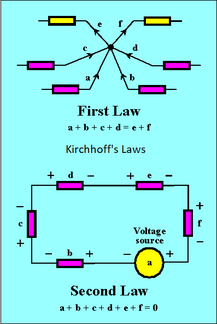
PWM (Pulse-Width Modulation): The digital control of how much time a signal spends in the on and off position, which can simulate a range of voltages, without actually changing the voltage, by using "pulses" of on-off states of maximum and minimum voltages. Circuit Diagram: A diagram that includes the connections of a circuit, without necessarily reflecting its physical position or orientation. Coding: A system of symbols that execute certain commands with the right format, like this sentence. It has a specified format, syntax, and "diction", if you will, depending on the coding language. Arduino: A programing language based around C and C++ Current (I or i): The flow of electricity through a circuit. Measured in Amperes, or colloquially Amps (A). I = R/V. When in Series, Current is the same through a circuit, but in parallel current splits inversely to resistance. Current is inversely proportional to Resistance. C~1/R. If C=3 then R is 3x less. Kirchhoff's 1st Law: Current In = Current Out. Ohms Law: V=IR. Voltage (V): The Potential Energy difference across a component is a circuit. (Voltage drops after encountering a component). Measured in Volts(V). V=IR. When in series, Voltage splits in proportion to Resistance, but in parallel, Voltage is the same. Resistance (R or r): Obstacle to the current that slows it down. (Quantity of slowing, measured by the object). Measured in Ohms (Ω). R=V/I. Resistance is inversely proportional to Current. R~1/C. So If R=3, then C will decrease by 3x, this is provable by Ohm's Law. Resistance is increased in a circuits using resistors and movable resistors like Potentiometers or "Pots" that work similar to dimmer switches. Knowing the properties of Current and Resistance and that C~1/R: When in Series, the total resistance is the sum of the individual components: R(total) = {R1+R2+R3+R4+Rn. . .). When in Parallel, the total resistance is the inverse of the individual components, summed: R(total) = {1/R1+1/R2+1/R3+1/Rn. . .). Power (P): Rate at which energy is transferred by a circuit. P = IV. |
|
Application of Priciples
|
Inquiry-Based Electricity Experiments: The first phase of this project was all about figuring out what circuits were, and how they worked, using alligator clips, AA and 9V batteries, battery holders, switches, resistors, LED pins, Ammeters, Voltmeters, and tiny incandescent bulbs. Within this phase operational definitions, theories and arguments, algebra, circuit diagrams, and fun frustration were made.
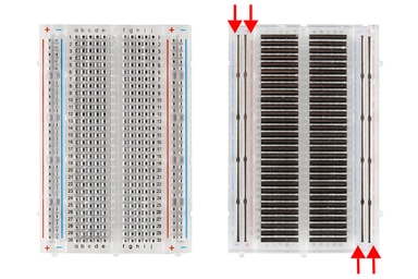
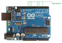
Breadboard Experiments: The second phase of the project included LED pins (R, G, B, and RGB), AA and 9V batteries, battery holders, switches, a broader range of resistors from 330Ω to 100KΩ, 22 guage jumper wires, Potentiometers, Capacitors, Multimeters, and 555 Integrated Circuit Chip Timers. In this phase we were proving and disproving our previous hypotheses, became more proficient with using circuit elements and building curcuits, and proved Kirchhoff's and Ohm's Laws. Coding: The third phase of the porject was using the Arduino Uno Board, the RedBoard, the knowledge gathered from the previous two phases for circuitry to make our circuits programable. Coding was learned using the Arduino IDE's (Integrated Development Environment) example sketches, kits, and the "SIK (SparkFun's Inventor's Kit) Guide" examples to learn code hands-on, and directly. It was at this stage where my partners and I had good rambling sessions about Arduino's map() function, baud rates, and the usage of Binary and Hexadecimal. |
Robot Art Show: The final phase of the project was to use all the skills we have developed to "make something cool". Our team initially decided on a light show, with synchronized music, but then we thought of making a 8-button keyboard, where chromatics can be added using a potentiometer, like a pitch-bend feature on 80's keyboards. Finally we decided to use combinations of notes to get chromatics instead of the potentiometer, as we thought the potentiometer would be less user-friendly.
|
A Simulation of the Adruino Keyboard
Arduino Keyboard Code
Reflection
Personally, I felt that this project went fine. There were grouping issues as I had to leave school to play at music festivals, which caused me to be at a different place than my original partner was. This made me work with people who were moving along at my pace. Initially i wasn't too well-adjusted with my new groupmates, but once I understood how they work, things were easier. Another issue that sprang up personally was being too caught-up on the details. I had spent too much time recording my observations and discussing my ideas, that I noticed I was dragging my partners down, and was getting behind. The tangents that my partners and I would get into are relevant to what we were learning, but the specificity of it, and researching it took time away. Towards the end of the project (three days), I realized I had to think like an engineer, who cares about functionality, and not like a scientist, where I examine the mechanics of functionality. But this thinking would be to our group's success later on as coding wasn't much of a challenge as our group understood it well. Other than these, I had fun, and thought our group did a fine job with communication, staying on-task, and critical thinking. But we should have been more aware of our time, and accomplished the given task without giving it too much debate and discussion.
- Nihal Nazeem.
- Nihal Nazeem.
